
|
Tubes Asylum Questions about tubes and gear that glows. FAQ |
Register / Login
|
In Reply to: Schematic needed for Valve ART VTA 70 posted by fxbill on May 15, 2009 at 19:17:44:
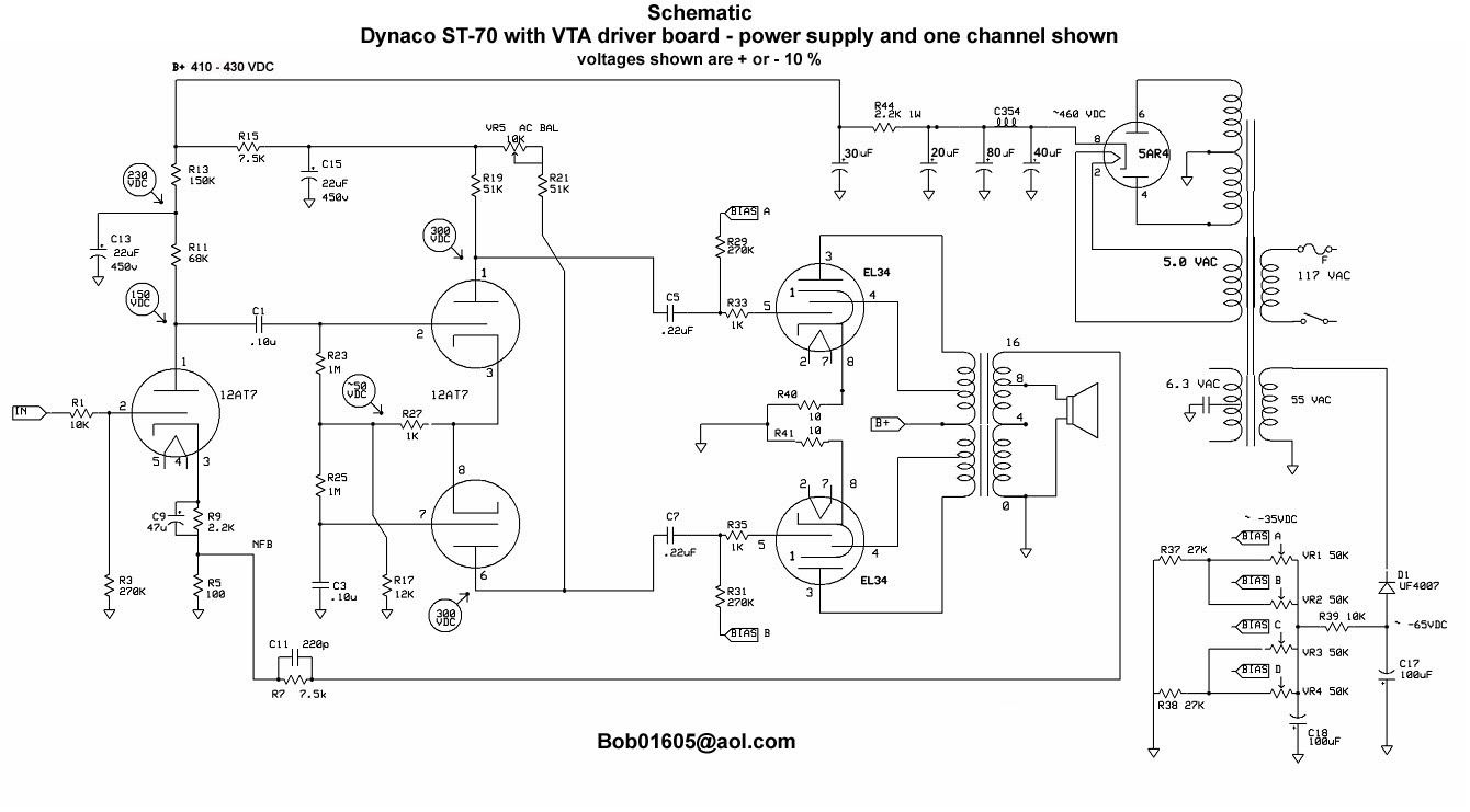
This is the schematic for the power supply and circuit for the LEFT channel of the VTA ST-70 which uses ODD numbered resistors and capacitors. The right channel is mirror of the left channel but uses EVEN numbered resistors and capacitors. This schematic shows the use of the CE Distribution 80, 40, 30, 20 quad cap in place of the stock Dynaco quad cap which was a 30 (right off pin 8 of the rectifier), 20, 20, 20 quad cap.
Bob Latino
This post is made possible by the generous support of people like you and our sponsors:
Follow Ups
- This is a schematic for the VTA ST-70 - Bob Latino 16:32:44 05/16/09 (0)
